Overview
The Falstad circuit simulator applet is a program which can be run in browser or downloaded and run locally. It provides a relatively intuitive user interface with enough power and sophistication to simulate fairly complex circuits. It does not contain a library of specific component profiles like Tina or a more dedicated circuit design package but the behaviour of a non-specific version of the component is normally adequate.
The home screen
Falstad will typically load with an oscillator circuit already running in simulation. Simply use "File" followed by "blank circuit" to clear it.

Figure: Falstad blank home window
Some of the controls are self-explanatory. For additional clarification, Simulation speed controlls how fast new data is generated and displayed within the simulation. Current speed independently changes only the animation speed of the electrical current pixels which itself still operates within the confines of the broader simulation speed.
Placing and connecting components
Assembling your circuit schematic is fairly intuitive. To place a component on the canvas select it drom the "Draw" menu. There are some basic options such as resistors or capacitors which have keyboard shortcuts. Most other components can be found in categories one would expect such as an AC source would be found in "Inputs and sources".

Figure: Falstad draw menu
Clicking and dragging will stretch the component between two connection nodes. The component generally doesn’t change size, only the wires at the end change in length so there is a minimum length requirement.

Figure: Falstad draw menu
You can use “Draw -> Wire” or just press the “w” key to draw basic wires.
Nodes in Falstad
Falstad only accepts node-to-node connections, meaning that connecting a wire to any point between two nodes will be marked with a red dot as invalid. Invalid nodes will count as disconnectedin the simulation.
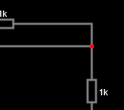
Figure: Falstad invalid node
Configuring components
To configure a placed component such as an AC source, double click on it whereupon you can change its basic properties.
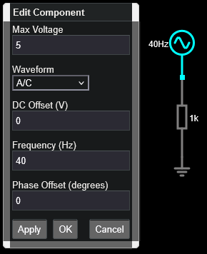
Figure: Configuration menu for an AC source.
Measuring voltages across components
To monitor the Voltage across a specific component over time, right click on that component and select “View in new scope” to add a real-time simulated oscilloscope probe across that component.
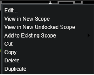
Figure: Right click menu to add voltage trace to new scope display.
The “Add to existing scope” option will present a sub-menu which lets you pick which scope display you want to add the new voltage trace to.
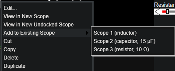
Figure: Adding to an existing scope can allow us to compare two signals more easily.
Exporting data for post-processing
To export data, you need to insert export points in the same place that you would put an oscilloscope probe.
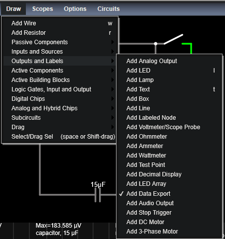
Figure: Adding export terminals to the circuit to export data.
When the export terminal has been placed it should resemble the image below. Note the node warning above applies here.

Figure: Example of a single export terminal placed onto a node before a resistor.
Remember that the voltage data on the export pin is the voltage value at that point in the circuit relative to ground. If you want to measure the voltage across a component whereupon the other side of the component isn’t connected to ground, you will need to add another export point and subtract the data accordingly.

Figure: Example of two export terminals placed so as to be able to work out the voltage drop across R1 (upper).
You need to run the simulation for a while before exporting or the files will be empty. To download the file, double left click on the export point and then click the hyperlinked file name. You may need to adjust the number of points a little to get the amount of data you want. I recommend renaming each file to something useful as you download them.

Figure: Export menu for a single data export terminal.
It is not made clear how long you need to wait to generate the desired number of data points but maxing out the sim speed for that task might be a reasonable way to make that wait time as short as possible.